How to setup a VLAN to share internet access whilst isolating the other VLAN’s.
Documentation for specific setups is pretty scarce for Netgear so we are sharing a basic (but common) configuration from start to finish.
Device:
Netgear GS724Tv4 switch.
Scenario:
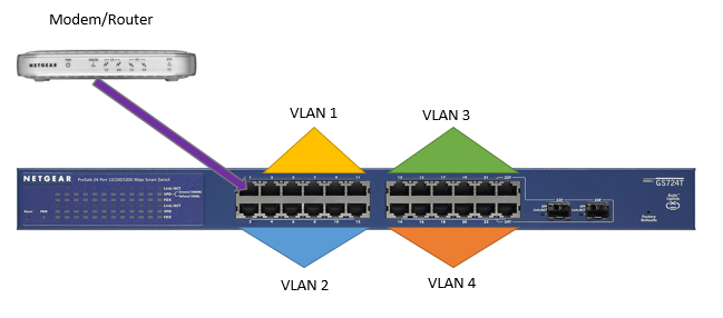
There is one internet connection via a standard Modem/Router combo device.
There are four business who need to share the internet connection.
To legally protect the businesses we want to isolate each business from the others.
Solution:
Create a VLAN for each of the businesses, allowing each to access the internet.
The network will look like the below:
How:
1. Install the Netgear Smart Control Center application from the installation CDROM that came with your Smart Switch.
If you don’t have the CD then find the IP of the switch via your routers DHCP allocation table or download the software by clicking here.
2. Connect the Netgear to power and connect your router’s LAN port (any will do) to PORT 1 on the Netgear SmartSwitch (Must be port 1)
Port 1 is configured as the DEFAULT port and will allow the internet to be shared to all other ports after we configure the VLANs.
3. Work out your Network Layout.
As we have four VLANs to configure and the ports are in four groups, we decided to allocate each port cluster to a VLAN as per below:
Preconfigured Ports:
VLAN 1 All Ports automatically assigned
VLAN 2 Default VoIP VLAN
VLAN 3 Default Video VLAN
Our VLANS
VLAN 10 Ports 1,3,7,9,11
VLAN 20 Ports 1,2,4,6,8,10,12
VLAN 30 Ports 1,13,15,17,19,21,23
VLAN 40 Ports 1,14,16,18,20,22,24
OK so let’s go!
Configuring the smart switch:
We’ve already connected the internet to port 1 and powered on the switch (Step 2 above)
Open the Netgear SmartControlCenter and click on ‘Discover’ to find your switch.
Click on the switch to select it then click on ‘Web Browser Access’ to launch the Web interface.

You will be prompted for the password in order to access the Graphical Interface.. The default password is ‘password‘
I would recommend setting a static IP Address for the Smart Switch so you can easily access it. This IP should match your host network.

Now lets add our VLAN’s
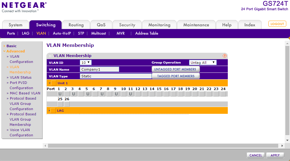
In the SWITCHING tab, select VLAN.
In the top field enter in your VLAN ID and a description of the VLAN to easily identify it.
The VLAN ID can be any unique number – We’ve selected VLAN 10,20,30 and 40.
Repeat the process for each VLAN you want to add.

Now we have created our 4 VLANs we need to assign ports to each one.
In the SWITCHING tab, select VLAN and then in the left column click on Advanced to expand the menu, then click on VLAN Membership
Leave the default VLANs as they are (for this scenario).
In the VLAN ID drop down list, select 10 (for VLAN 10)
You’ll see a list of all the ports on the switch and they will all be blank.
When designing the network layout, VLAN 10 had Ports 1,3,7,9,11 assigned. Double click each port so that a ‘U’ is displayed in the relevant ports as per below then click APPLY
Repeat the process for each VLAN until all done.
If we connect a community printer that is required by all businesses, we’d simply add the port to the required VLAN’s here also. So if we conenct a printer to port 24, just add that port into each VLAN that requires the access to the printer.
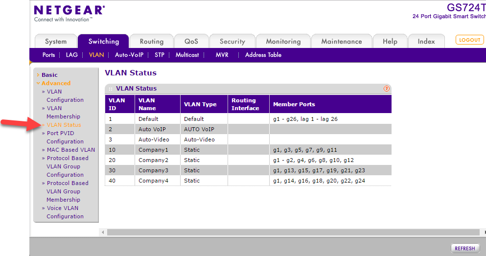
When completed click on VLAN Status to double check everything, it should look as per below (for our setup).
Next we need to isolate each VLAN from the other VLAN’s.
Click on Port PVID in the left menu
Let’s configure VLAN 10 (ports 3,5,7,9,11 – Don’t tick port 1, this is correctly configured already.
Put a tick to the left of each of the required ports
Type 10 in the ‘Configured PVID (1 to 4093)’ field at the top of the table.
Click APPLY
Repeat for the other VLANs
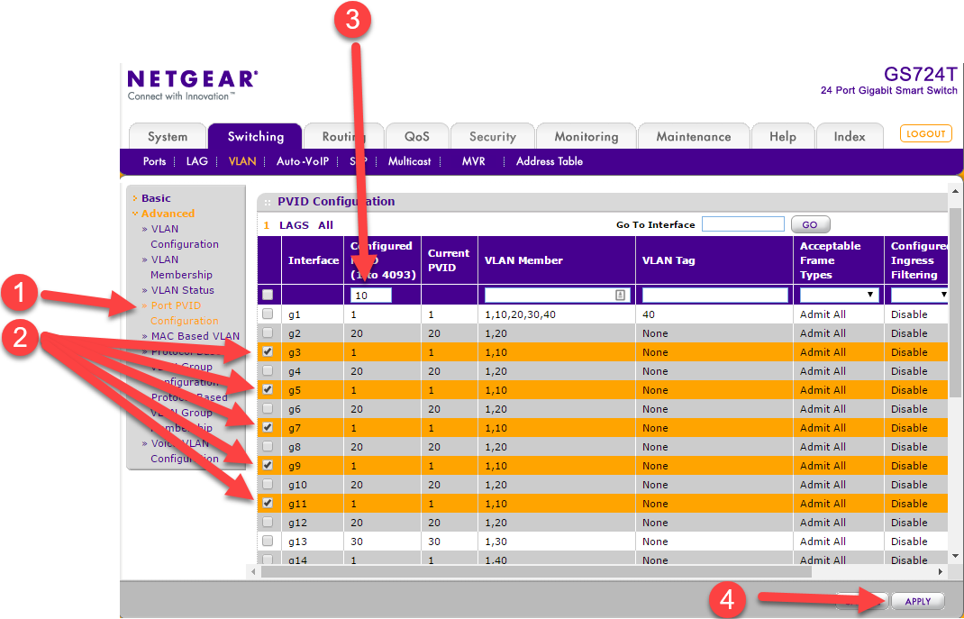
Now this is completed it should look as per below:
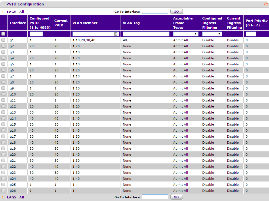
At this stage your VLANs sould be isolated from each other.
Easy test – plug two laptops into VLAN 10 and get a ping happening (ping 192.168.200.x -t) and you should get a response.
Now move one to VLAN 20 and the ping should fail.
Now test internet access on both. If you don’t have internet access then its likely you left port 1 empty during port assignments.
Repeat on VLAN 20 and VLAN 30.
If you plug a laptop into port 1, you’ll be able to ping/access anything on ports 2 to 24.
You can add a switch onto any of the VLAN ports to expand the number of ports or if you want to add a Wi-Fi AP for each company.
Hope this saves you some time 🙂